A Guide to the Application of CORTEX
Laser Scanning and Diffraction Gauges
General:
The DG (Scanning Laser Gauge) and WG (Laser Wire Gauge) type instruments
manufactured by CORTEX Research and
Development Ltd. can measure the outside diameter of cylindrical objects,
such as rods, tubes, cables, wires or fibres. The measurement is fast (up to
200 measurements/sec), precise and contact-free. The diameter range spanned by
these instruments is from 10 micrometer to 50 mm.
Both instrument
types (DG and WG gauges) are similar in that they basically consist of a Measuring Head and an industrial PC
based Control Unit with a keypad and
colour LCD monitor. One control unit can handle one or two measuring heads,
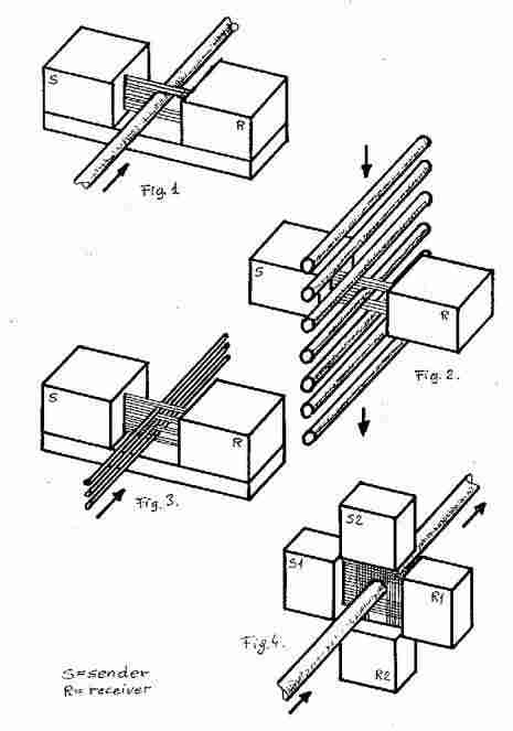
depending on the application. The layout of these heads is similar in that there
is a sender and a receiver part, and the object to be measured is placed
between them (Fig. 1).
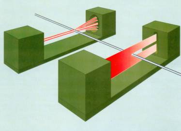
Measuring principles:
The WG Laser Wire Gauges have a stationary
laser beam. The object to be measured is placed into the laser beam and diffracts (scatters) the light beam.
The diffraction pattern is detected in the receiver head via a one dimensional CCD light sensor, digitised and
evaluated by the control unit to obtain the diameter of the object. This principle is
especially suited for objects of small diameter, such as wires or fibres.
The sender part
of the DG Scanning Laser Gauges
produces a scanning (up-down moving)
laser beam (vertical line) and the object to be measured is placed into this
beam and its „shadow” is detected at the receiver part. This principle is used
for measuring larger diameter objects.
Application of the WG1C Laser
Wire Gauge :
The typical
application of the WG Laser Wire Gauges is the measurement of very thin
objects, such as copper, tungsten and molybdenum wires. The typical diameter
ranges are 10 - 500 m but diameters up to 1 mm
(optionally 2 mm) can be measured.
The basic
function of these instruments is to measure and display the wire diameter and to
classify it according to programmed parameters (typically nominal diameter and
tolerances). This can be extended with several options, such as SPC (Statistical Process Control)
evaluation, analogue outputs (e.g. for chart recorder or process control),
interfacing to a drawing or spooling machine to qualify a given length (spool)
of wire either during manufacture or at the Quality Control of the finished
product.
Normally one
measuring head is connected to a control unit, however if required two measuring heads can also be
connected. This makes the following applications possible (depending on the
software of the control unit):
·
Two independent diameter measurements at approximately the same location
(cost effective solution).
·
Measurement of the same wire at two different manufacturing stages (e.g. copper wire
without and with lacquer layer).
·
Measurement of the same wire in two orthogonal directions to obtain ovality data.
Application of the DG Scanning
Diameter Gauges
The application
of the DG Scanning Diameter Gauges are very widespread.
Basically two
types of gauges are available: The DG1C
Gauge performs precise measurements with 0.1 m resolution and works in the 0,05 -
10 mm measuring range (20 mm on special request), while the DG50C Gauge has a resolution of 1 m and a 1 ‑ 50 mm
measuring range.
The main
application of the DG1C Gauge is the QC of
wires and cables or small machined parts during or after the manufacturing
stage.
The DG50C Gauge can be used for similar
measuring purposes for diameters up to 50 mm in harsh industrial environments.
All the options
mentioned before (analogue outputs, double measuring heads, interfaces etc.)
can be applied in the case of the Scanning Diameter Gauges as well.
Some of the
most frequent applications are:
·
Continuos diameter measurement of copper, tungsten and molybdenum wires
during and after manufacture
·
Measurement of cables
·
Measurement of plastic rods and tubes
Application of Diameter Gauges
in glass tube manufacture
The DG50C
device has found wide spread use in the glass
industry for measuring glass tube. A special characteristic of CORTEX equipment is that a reference signal is inputted from the glass
cutter, which enables the gauge to classify and
sort (usually via solid state relays) the
cut-up glass tubes while the measurement is performed on the continuos tube
on the drawing line, before the cut is made.
A further
option is a 4-20 mA Proportional and/or
PID control signal output for process control.
Thus one diameter gauge placed on the drawing line can provide the
following functions, usually performed by several gauges:
·
Measure and display of the continuos
tube diameter
·
Classification and sorting of the
cut up glass tubes according to several tolerance classes
·
PID process
control signal (for air-blow or drawing speed regulation)
·
Data collection (standalone or
by monitoring PC via serial line).
The measuring
systems can be expanded with the following measuring options:
·
Laser measuring system for sensing glass
imperfections (knots and stones) in glass tubes
·
Vision system for measuring the bow
(curvature) of cut up glass tubes
·
Measurement of wall thickness
of glass tubes
Special Applications of the DG Scanning
Diameter Gauges
Below we list
some of the special applications developed so far for the diameter gauges:
·
Measurement of cut up glass tubes for compact
fluorescent lighting sources (CFL). In this special application only one
head is used, but the glass tubes travel parallel to the laser scan direction
and also rotate. Thus as the tube traverses the measuring range, its diameter
is measured at different angles of rotation, which enables to sort the piece according
to both the diameter and ovality into different tolerance classes (Fig. 2).
This system can be extended with the measurement of tube-end tilt and tube length to provide complete QC of the product.
·
Measurement of several wires
with one gauge (Fig. 3).
·
X-Y head
arrangement for the measurement of ovality of wires (DG1C), glass tubes and hot
rolled iron rods (DG50C) (Fig. 4).
·
Measurement and control of steel
rods on the grinding machine. In this application the grinding machine step
motor is directly steered with programmable parameters by the control unit
according to the difference between the measured and nominal diameter.
Data Collection
Option:
All diameter measuring instruments
can be supplied as an option in a special version for data acquisition. The functions of the software
typically include SPC data acquisition,
display and data logging according to work shifts and tube types. Alternatively
several WG and/or DG devices can be linked to an overhead
monitoring-evaluation system (PC) by the standard serial interface (RS232
or RS485) or via local computer network (Ethernet) for similar data collection
purposes. Special software for a given application can be developed on request.
Figures: